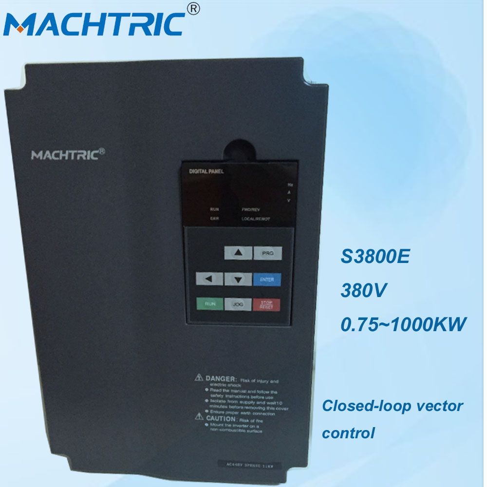
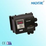
Item | S3800E | S3800E |
| Based functions | Control mode | V/F(Voltage/Frequency) control |
| Sensorless flux vector control (VC) |
| Closed-loop vector control (CVC) |
| Maximum frequency | Vector control: 0-320 Hz |
| V/F control: 0-3200Hz |
| Carrier frequency | 1.0-16.0 kHz |
| The carrier frequency is automatically adjusted based on the load features. |
| Input frequency esolution | Dgital setting: 0.01 Hz |
| Analog setting: 0.025% of maximum frequency |
| Startup torque | G type: 0.5 Hz/150% (VC); 0 Hz/180% (CVC) |
| P type: 0.5 Hz/100% |
| Speed range | 1:100 (VC) |
| 1:1000 (CVC) |
| Speed stability accuracy | ± 0.2% (VC) |
| ± 0.02% (CVC) |
| Torque control accuracy | ± 5% (CVC) |
| Overload capacity | G type: 60s for 150% of the rated current, 3s for 180% of the rated current. |
| P type: 60s for 120% of the rated current, 3s for 150% of the rated current. |
| Torque boost | Auto boost |
| Customized boost 0.1%-30.0% |
| V/F curve | Line V/F curve |
| Multi-point V/F curve |
| N-power V/F curve (1.2-power, 1.4-power, 1.6-power,1.8-power, square) |
| V/F separation | two types: complete separation; half separation |
| Ramp mode | Straight-line ramp |
| S-curve ramp |
| Four groups of acceleration/deceleration time with the range of 0.0-6500.0s |
| DC braking | DC braking frequency: 0.00 Hz to maximum frequency |
| Braking time: 0.0-100.0s |
| Braking action current value: 0.0%-100.0% |
| JOG control | JOG frequency range: 0.00-50.00 Hz |
| JOG acceleration/deceleration time: 0.0-6500.0s |
| Onboard multiple preset speeds | It implements up to 16 speeds via the simple PLC function or combination of terminal states |
| Onboard PID | It realizes process-controlled closed loop control system easily. |
| Auto voltage | It can keep constant output voltage automatically when the mains voltage changes. |
| regulation (AVR) |
| Overvoltage/ Overcurrent stall control | The current and voltage are limited automatically during the running process so as to avoid frequent tripping due to overvoltage/over current. |
| Torque limit and control | It can limit the torque automatically and prevent frequent over current tripping during the running process.Torque control can be implemented in the CVC mode. |
| Individualized functions | Support for multiple PG card | Support for rotating transformer PG card,differential input PG card, UVW differential input PG card, resolver PG card and OC input PG card |
| Power dip ride through | The load feedback energy compensates the voltage |
| reduction so that the AC drive can continue to run for a |
| short time. |
| Rapid current limit | It helps to avoid frequent over current faults of the AC drive. |
| High performance | Control of asynchronous motor and synchronous motor are |
| implemented through the high-performance current vector |
| control technology. |
| Timing control | Time range: 0.0-6500.0 minutes |
| Communication methods | MODBUS-RTU,PROFIBUS-DP,CAN |
| Protection mode | Motor short-circuit detection at power-on, input/output |
| phase loss protection, over current protection, overvoltage |
| protection, under voltage protection, overheat protection and overload protection. |
| Input and output | Input terminal | 8 digital input terminals, one of which supports up to |
| 100 kHz high-speed pulse input. |
| 2 analog input terminals, one of which only supports |
| 0-10 V voltage input and the other supports 0-10 V voltage input or 4-20 mA current input. |
| Frequency source | Digital setting, analog voltage setting, analog current setting, pulse setting and serial communication port setting. |
| Auxiliary frequency source | There are ten auxiliary frequency sources.It can implement |
| fine tuning of auxiliary frequency and frequency synthesis. |
| Running command source | Operation panel/Control terminals/Serial communication port |
| You can perform switchover between these sources in |
| various ways. |
| Output terminal | 1 high-speed pulse output terminal (open-collector) that |
| supports 0-100 kHz square wave signal output |
| 1 digital output terminal |
| 2 relay output terminal |
| 2 analog output terminal :that supports 0-20 mA current output or 0-10 V voltage output |
| operation on the operation panel | LED display | It displays the parameters. |
| Key locking and | It can lock the keys partially or completely and define the |
| function selection | function range of some keys so as to prevent mis-function. |
| Optional parts | Rotating transformer PG card,differential input PG card, UVW differential input PG card, resolver PG card and OC input PG card |
| Environment | Installation location | Indoor, free from direct sunlight, dust, corrosive gas, |
| combustible gas, oil smoke, vapour, drip or salt. |
| Altitude | Lower than 1000 m |
| Ambient temperature | -10°C ~40°C (de-rated if the ambient temperature is |
| between 40°C and 50°C) |
| Humidity | Less than 95%RH, without condensing |
| Vibration | Less than 5.9 m/s2 (0.6 g) |
| Storage temperature | -20°C~60°C |