1.0 | Manufacturer/Country | - | - Equipment that are compliant with KEMA, KERRI or CESSI Certifications. (Attach Certificates and Type Tests report from STL Members only) | YES |
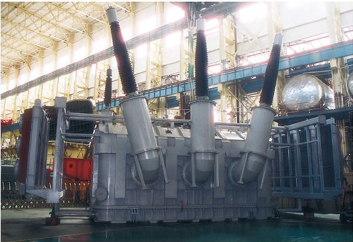
1.1 | Type | - | Three-phase | OSFSZ-165000/330 |
1.2 | Class | | - | - |
2.0 | Rated data and characteristics | | | |
2.1 | Rated power: - primary/secondary
- tertiary | MVA
MVA | 150/165
30 | 165/165 30 |
2.2 | Cooling | - | ONAN/ONAF | ONAN/ONAF |
2.3 | Rated voltage - HV winding
- LV winding
- tertiary winding | kV
kV
kV | 330
132
33 | 330 132 33 |
2.4 | Tap changer: - type
- on-load tap changer location
- regulating range
- rating | -
%
- | Oil/Vacuum HV Neutral side
+4 x 1.25%
-12 x 1.25%
Rated power on all taps | Oil HV Neutral side
+4 x 1.25%
-12 x 1.25%
Rated power on all taps |
2.5 | Frequency | Hz | 50 | 50 |
2.6 | Connection of the three-phase windings (group of vectors IEC 76) | - | YN,a0,d11 | YN,a0,d11 |
2.7 | Rated current at ONAF rated power and rated voltage tap: | | | |
| - HV winding
- LV winding
- tertiary winding | A
A
A | 283
704
53 | 289 722(LINE)/433(PHASE) 303 |
2.8 | No-load current through: - HV winding
- LV winding
- tertiary winding | A
A
A | @100% ≤0.4(max)
≤0.6(max)
≤0.6(Max) | @100% ≤0.4(max)
≤0.6(max)
≤0.6(Max) |
2.9 | Short circuit impedance | | Base: rated voltage and 150 MVA | Base: rated voltage and 165 MVA |
2.9.1 | Direct impedance at nominal voltage tap: - HV/LV
- HV/TV
- LV/TV | %
%
% | 15
50
33 | 15 50 33 |
2.9.2 | Direct impedance at minimum voltage tap: - HV/LV | % | 15 | 11.0 |
2.9.3 | Direct impedance at maximum voltage tap: - HV/LV | % | 15 | 16.3 |
2.9.4 | Zero sequence impedance at nominal voltage tap | % | 10,47 | |
| - HV / LV
- HV / TV
- LV / TV | %
%
% | -
-
- | -
-
- |
2.10 | Tolerance to be applied to the short circuit impedance, in terms of % of the guaranteed value on: | | | |
| - nominal voltage tap
- other taps | %
% | +5
-15 | +5
-15 |
2.11 | Transformer capacity to withstand external short circuits: | | | |
2.11.1 | Short circuit duration | S | 2 | 2 |
2.11.2 | Symmetrical short circuit current withstand during the indicated period and asymmetrical short circuit withstand: | | | |
| - HV winding | kA RMS
kA (peak) | -
100kA/2s | -
100kA/2s |
| - LV winding | kA RMS
kA (peak) | 60kA/2s | 60kA/2s |
| - tertiary winding | kA RMS
kA (peak) | 31.5kA/2s | 31.5kA/2s |
| - pre-fault voltage | p.u. | 1.05 | 1.05 |
2.12 | Guaranteed losses | | | |
2.12.1 | No-load losses at rated voltage and frequency, with rated voltage tap | kW | ≤71.5 | ≤71.5 |
2.12.2 | No-load losses at 110% of the rated voltage, at rated frequency and rated voltage tap | kW | ≤87.8 | ≤130 |
2.12.3 | No-load losses capitalized value | US $/kW | 3000 | 3000 |
2.12.4 | Tolerance to be applied to no-load losses
(in % of the guaranteed value) | % | 10 | 10 |
2.12.5 | On-load losses at rated voltage and frequency, with rated voltage tap and ONAN rating:
- HV winding
- LV winding
- tertiary winding At (165MVA) |
kW
kW
kW
KW |
-
-
-
≤276 | -
-
- ≤360 |
2.12.6 | On-load losses capitalized value | US $/kW | 3000 | 3000 |
2.12.7 | Tolerance to be applied to total losses (in %of the guaranteed value) for all the windings | % | 10 | 10 |
2.12.8 2.12.9 | Auxiliaries consumption at second stage of cooling (ONAN/ONAF) Efficiency at 75deg at: unity P.F. - 100% loading
- 75% loading
- 50% loading
0.8 P.F. 1. 100% 2. 75% 3. 50% | kW % % % % % % | - ≥99.7 ≥99.6 | - 99.73% 99.67% |
2.13 | Highest voltage for equipment: - HV winding
- LV winding
- tertiary winding | kV
kV
kV | 362
145
36 | 362 145 36 |
2.14 2.14.1 | Rated insulation level: Short time power frequency withstand: - HV winding - line terminal
- LV winding - line terminal
- neutral
- tertiary winding
- control wiring | kV RMS
kV RMS
kV RMS
kV RMS
kV RMS | 650
275
38
70
2.0 | 510 275 38 70 - |
| | | | |
2.14.2 | Basic impulse level: | | | |
| - HV winding - line terminal
- LV winding - line terminal
- neutral point
- tertiary winding | kV (peak)
kV (peak)
kV (peak)
kV (peak) | 1050
650
125
145 | 1050 650 125 145 |
2.14.3 | Basic switching surge level HV winding ( Line-to-Ground/Line-to-Line ) | kV (peak) | 850/1275 | 850/- |
2.15 | Temperature rise limits at maximum power output at ONAN and ONAF ratings and at lowest voltage tap and corresponding voltage: | | | |
| - top oil at ambient temperature - average copper at ambient temperature - hot spot windings | K
K K | 45
55 68 | 45 55 68 |
2.16 | Permissible overload in emergency cases: - Maximum continuous overload based on highest winding temperature which exceeds by 5oC the guaranteed limit | MVA | | |
| - Maximum continuous over voltage based on the specified temperature rise limits (in % of the rated voltage) | % | 5 | 5 |
2.17 | Oil: - manufacturer
- type
- data sheet attached | -
-
- | NYNAS NYTRO 10XN (Inhibited) (IEC 60296) -
-
- | NYNAS NYTRO 10XN (Inhibited) (IEC 60296) |
2.18 | Bushings | | | |
2.18.1 | HV bushings: - class
- manufacturer
- type designation
- rated current
- short circuit withstand
- basic insulation level
- basic switching surge level
- power frequency withstand for 1 minute
- connectors for
- creepage distance | kV
-
-
A
kA RMS
kV (peak)
kV (peak)
kV RMS
-
mm/kV | 420
-
-
2500
100kA/2s
1425
1175
650
TBA
31 | 550 XD BRDLW 2500 100kA/2s 1800 1300 790
TBA 31 |
2.18.2 | LV bushings: - class
- manufacturer
- type designation
- rated current
- short circuit withstand
- basic insulation level
- power frequency withstand for 1 minute
- connectors for
- creepage distance | kV
-
-
A
kA RMS
kV (peak)
kV RMS
-
mm/kV | 145
-
-
750
60kA/2s
750
325
TBA
31 | 170 XD BRDLW 1250 60kA/2s 750 340 TBA
31 |
2.18.3 | Tertiary bushings: - class
- manufacturer
- type designation
- rated current
- short circuit withstand
- basic insulation level
- power frequency withstand for 1 minute
- connectors for
- creepage distance | kV
-
-
A
kA RMS
kV (peak)
kV RMS
-
mm/kV | 36
-
-
-
-
170
70
TBA
31 | 40.5 XD BRDLW 1600 200 80 TBA
31 |
2.18.4 | Neutral bushings: - class
- manufacturer
- type designation
- rated current
- short circuit withstand
- basic insulation level
- power frequency withstand for 1 minute
- connectors for
- creepage distance | kV
-
-
A
kA RMS
kV (peak)
kV RMS
mm/kV | 170
-
-
1250A
50kA/2s
750
325
-
31 | 170 XD BRDLW 1250 50kA/2s 750 340 -
31 |
2.19 2.19.1 | Design data: Maximum flux density in the columns at: - rated voltage
- 105% of the rated voltage | tesla
tesla | 1.5
1.58 | 1.7 1.79 |
2.19.2 | Maximum flux density in the yokes at: - rated voltage
- 105% of the rated voltage | tesla
tesla | 1.5
1.58 | 1.7 1.79 |
2.19.3 | Maximum current density at ONAN rated power and rated voltage tap: - HV winding
- LV winding
-Tertiary winding |
A/mm2
A/mm2
A/mm2 |
1.4-1.9 2.2-2.9
TP | 1.9 2.5 |
2.19.4 | Winding resistance: - HV winding
- LV winding
-Tertiary winding | ohms
ohms
ohms | -
-
- | 0.64 0.20 0.10 |
2.19.5 | Voltage regulation at ONAN rating and rated voltage tap (in % of the rated voltage): - With unity power factor:
. LV side
. TV side |
%
%
|
-
-
|
-
-
|
| - With 0.9 power factor (lagging):
. LV side
. TV side |
%
%
|
-
-
|
-
-
|
| - With 0.8 power factor (lagging):
. LV side
. TV side |
%
%
|
-
-
|
-
-
|
2.19.6 | Primary exciting current, LV side: - at 0.01 second
- at 0.1 second | kA
kA | -
- | -
- |
2.19.7 | Core silicon steel grade (core or shell) | - | CORE:(23M-OH /23ZDKH) | CORE |
2.19.8 | Winding conductor | - | Copper | Copper |
2.20 | Audible noise level | | | |
| - Voltage in percent of rated value
- ONAN rating
- ONAF maximum rating | %
dB(A)
dB(A) | 105
≤83 max
≤86 max | 105 ≤83 max()
≤86 max()
|
2.21 | Radio Interference Voltage at 0.5 MHz
as per IEC 694 | mV | ≤2500 max
| ≤2500 max
|
3.0 | Weights and dimensions | | | |
3.1 | Total weight of transformer, equipped for service | Kg | - | 236000 |
| | | | |
3.2 | Weight: - oil
- core and coil assembling
- tank and accessories
- net copper
- net core steel | kg
kg
kg
kg
kg | -
-
-
-
- | 74000 98000 64000 34000 55000 |
3.3 | Maximum shipping weight (heaviest item) | Kg | - | 132000() |
3.4 | Height from foundation to: - highest point of HV bushing
- highest point of tank
- highest point of conservator tank
- highest point of lifting hook to remove
core and coil assembly | mm
mm
mm
mm |
-
-
-
| 8800 3300 6900 8500 |
3.5 | Outline dimensions: - length
- width | mm
mm | -
- | 14600 7200 |
3.6 | Layout drawing no | - | To be enclosed
with bid | |
3.7 | Maximum shipping dimensions of tank: - outside height
- outside width
- outside length | mm
mm
mm | -
-
- | 10200 3800 3300 |
3.8 | Transportation drawing no | - | To be enclosed
with bid | |
4.0 | On-load tap changer | | | |
4.1 | Manufacturer | - | MR REINHAUSEN GERMANY | MR GERMANY |
4.2 | Type | - | Oil | Oil |
4.3 | Rated through current | A | - | 600 |
4.4 | Number of steps | - | 17 | 17 |
4.5 | Short circuit withstand | kA RMS | 8 | 8 |
4.6 | BIL to ground | kV (peak) | 750 | 750 |
4.7 | Power frequency withstand voltage for 1 minute | kV RMS | 325 | 325 |
4.8 | Tap transition device | - | Jansen | |
4.9 | Parallel automatic controller | - | Master-follower | Master-follower |
5.0 | Current transformer incorporated into the power transformer | | | |
5.1 5.1.1 5.1.2 5.1.3 | CT in HV phase bushings: Number of cores per bushing Primary rated current Secondary rated current | - A A | 2 400 1 | 2 400 1 |
5.1.4 | Accuracy class: - protection - metering | -
- | To be coordinated (1)5P20, 20 VA
(1)CL0.2, 20 VA | (1)5P20, 20 VA
(1)CL0.2, 20 VA |
5.1.5 | Ratio | - | 400:1 | 400/1 |
5.1.6 | Short circuit withstand | A | 100kA/2s | - |
5.1.7 | Continuous secondary current thermal limit | A | - | - |
5.2 | CT in LV phase bushings: | | | |
5.2.1 | Number of cores per bushing | - | 2 | 2 |
5.2.2 | Primary rated current | A | 800 | 800 |
5.2.3 | Secondary rated current | A | 1 | 1 |
5.2.4 | Accuracy class:
- protection
- metering
| -
-
-
| To be coordinated (1) 5P20, 20 VA, (1)CL0.2, 20 VA | (1) 5P20, 20 VA, (1)CL0.2, 20 VA |
5.2.5 | Ratio | - | 800/1 | 800/1 |
5.2.6 | Short-circuit withstand | A | 60kA/2s | - |
5.2.7 | Continuous secondary current (thermal limit) | A | - | - |
5.3 5.3.1 5.3.2 5.3.3 5.3.4 | CT in LV neutral bushing: Number of cores per bushing Primary rated current Secondary rated current Accuracy class - protection (to be coordinated) | - A A - | 2 800 1 (1) 5P20, 20 VA | 2 800 1 (1) 5P20, 20 VA |
5.3.5 | Ratio | - | 800:1 / 400:1 | 400-800/1 |
5.3.6 | Short circuit withstand | A | - | - |
5.3.7 | Continuous secondary current (thermal limit) | A | - | - |
5.4 5.4.1 5.4.2 5.4.3 5.4.4 | CT in tertiary phase bushings: Number of cores per bushing Primary rated current Secondary rated current Accuracy class: - protection | - A A - | 2 800 1 (2) 5P20, 20VA | 2 800 1 (2) 5P20, 20VA |
5.4.5 | Ratio | - | 800:1 | 800/1 |
5.4.6 | Short circuit withstand | A | - | - |
5.4.7 | Continuous secondary current (thermal limit) | A | - | - |
6.0 | Layout | | | |
6.1 | Primary winding bushings | - | (3) Long. Axis | Long. Axis |
6.2 | Secondary winding bushings | - | (3) Long. Axis (opposite to HV) | Long. Axis (opposite to HV) |
6.3 | Tertiary winding bushings | - | (3) Transv. Wall in junction box | Transv. Wall in junction box |
6.4 | Conservator tank | - | Transv. Axis | |
6.5 | Tap changer | - | Transv. Axis | |
6.6 | Control cabinet | - | - | |
6.7 | Radiators | - | - | |
6.8 | Terminal block connection drawing | - | As per enclosed drawings | |
7.0 | Standards | | Latest revision of IEC 60296 | Latest revision of IEC 60296 |
7.1 | Manufacturing | - | IEC 60044
IEC 60076
IEC 60137
IEC 60214
IEC 60529
IEC 60815
IEC 60947
NEMA TR-1 | IEC 60044
IEC 60076
IEC 60137
IEC 60214
IEC 60529
IEC 60815
IEC 60947
NEMA TR-1 |
7.2 | Quality assurance | - | ISO------------ | ISO------------ |
8.0 | Installation | - | Outdoor in substation yard | Outdoor in substation yard |
9.0 | Type test report | | Copy of type test for similar transformer to be included with the bid | Copy of type test for similar transformer to be included with the bid |
| | | | |