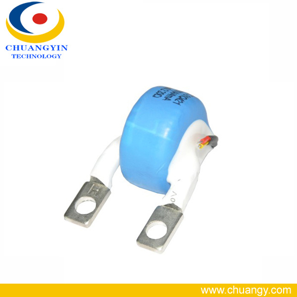
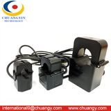
| Prod Model: |
Mini current transformer |
| Housing Material: |
Flame Retardant ABS |
| Encapsulation: |
Epoxy Resin |
| Ambient Temperature: |
-40 to +75 Celsius Degree |
| Dielectric Strength: |
4000VAC 1mA 60s |
| Application: |
Energy Meter |
| Accuracy Grade: |
Class0.1, Class0.2 |
Product Description
Features
Adopted high pemeability core
High accuracy
Excellent linearity performance
Miniature size
Easy to install
DC immunity function
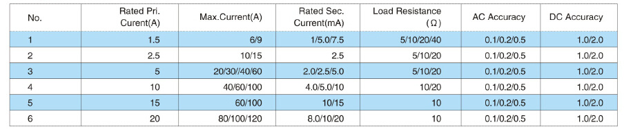
Specification
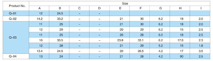
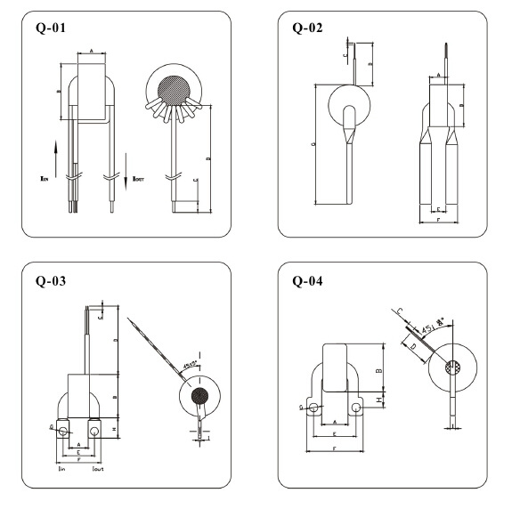
Dimension
Note:
The above parameter is only for reference as typical data, customer-made is subject to customers' request.
SHENZHEN CHUANGYIN TECHNOLOGY CO., LTD.
( CY Group )
Certification: KEMA, ISO9001, UL, SGS, CE.
( Your reliable partner for CT,PT (up to 72.5KV) ,Cable accessories, Split core CT, Rogowski Coil , Latching Relay, Flx-core CT )
Arvin Q.
Business Development Executive
Mob: +86 13925284622
Address: 1st Floor, Building B, Jiada R&D Building, No.5 Songpingshan Rd., Shenzhen High-Tech Zones, Nanshan, Shenzhen, China,
Post code: 518057
Tel: +86 0755-86000716/ 86007806
Fax: +86 0755-86000614
Web: www.chuangy.com
Current transformers for Energy Meter
1.Technical Data
(1) AC Tolerance
Below format is the range of phase error and ratio error at rated frequency and load:| Accuracy | Rated Current Percentage | Tolerance Range |
| Ratio Error (%) | Phase Error (%) |
| 0.01 | 5 | ±0.02 | ±0.6 |
| 10-120 | ±0.01 | ±0.3 |
| 0.02 | 5 | ±0.04 | ±1.2 |
| 10-120 | ±0.02 | ±0.6 |
| 0.05 | 5 | ±0.10 | ±4 |
| 10-120 | ±0.05 | ±2 |
| 0.1 | 5 | ±0.40 | ±15 |
| 10 | ±0.25 | ±10 |
| 20 | ±0.20 | ±8 |
| 100-120 | ±0.10 | ±5 |
| 0.2 | 5 | ±0.75 | ±30 |
| 10 | ±0.50 | ±20 |
| 20 | ±0.35 | ±15 |
| 100-120 | ±0.20 | ±10 |
| 0.5 | 5 | ±1.50 | ±90 |
| 10 | ±1.00 | ±60 |
| 20 | ±0.75 | ±45 |
| 100-120 | ±0.50 | ±30 |
| 1.0 | 5 | ±3.00 | ±180 |
| 10 | ±2.00 | ±120 |
| 20 | ±1.50 | ±90 |
| 100-120 | ±1.00 | ±60 |
A. Ratio Error
It means the error while testing current. It caused by difference between actual current ratio and rated current ratio. It can be calculated in accordance with the following formulas.Current Error = [ 100 ( Knls - Ip) / Ip ] %Kn: Rated current ratio;Ip: Actual primary current (unit: A)Is: Actual secondary current while doing test by input Ip. (unit: A)B. Phase Error
It means the phase position difference between vector of primary current and vector of secondary current. Vector direction is subject to ideal current transformer whose phase error is zero. If secondary current vector is ahead of primary current vector, then phase error is positive number. Its unit is usually sub-arc or arc. Note: This definition is based on sinusoidal current (2) DC Tolerance
In normal condition, the power net is sinusoidal AC at loop, positive waves are symmetry. But in some special conditions, the circuit have DC, then positive and negative waves will not be symmetry. Common current transformer would be saturation under this condition, and the meter used this CT have large error, even can not work.So just DC Immunity CT can solve this problems. As following figure to test the DC error , 01 accuracy CT will be controlled within ±3.0%, 0.2 accuracy class CT will be controlled within ±6.0%. (3) Insulation Strength
Pri.-Sec.: AC4000V, 60s, 1mA(4) Insulation Resistance
Pri. Winding to Sec. Winding ≥ 1000MΩ (DC500V) 2. PT (current type) used for power parameter transducer
HPT001-HPT006 is serial of current type Voltage transformer, widely utilized for power transmitter, power parameter transducer, etc. Typical application circuit diagrams as below shows. Max. Input and output current ratio is 1:1, Max. Input current is 10mA, max primary input voltage less than 1000V ( connect with current - limiting resistor ). Ratio error is ±0.1% and phase error is ±10, Loading Resistance is 0. Diagram 1, secondary loading resistance is 0 ( approx ). The measured input voltage (VIN) by current-limiting resistor (RIN) generated 0~2mA current through out PT. PT sense similar 0~2mA, through calculate amplifying, adjust the resistor value (R), resulting required output voltage.Diagram 2, parallel connecting resistor (R) output circuit, Resistor (R) below 500Ω (max. Output voltage 1.5V). As the high burden, so the phase error is higher. But the linearity is basically unchanged. 3. Typical Application of CT
With big output signal and high accuracy, current transformer is use in energy meter widely.(1) CT used for single phase energy meter (diagram 1)
Diagram 1, CT sampling from current signal, working principle is a shunt resistor, compare to current inductor (eg. Current Transformer). The resistor is advanced in low power consumption, which is more convenient for low current meter), Normally CT's output can connect ADE7755 through channel V1. V1 is fully differential voltage input channel, VIIP is input positive terminal , V1N is input negative terminal. Under special condition, the max differential signal of channel V1 is ±30mV (Similar as AGND), for normal application, it is ±6.25mV. Resulting required output voltage. Diagram 2, parallel connecting resistor (R) output circuit, Resistor (R) below 500Ω (max. Output voltage 1.5V). As the high burden, so the phase error is higher. But he linearity is basically unchanged.(2) CT used for single phase energy meter (diagram 2)
Diagram 2, CT1, CT2, CT3 simple from A, B, C three phase current separately, inputting with three pairs of differential voltage, which are IAP, IAN; IBP, IBN; ICP, ICN. The max voltage single ratio is ±0.5V among three. Current channel contains Programmable Gain Amplifier (PGA1), Amplifier' again is 1, 2 or 4. Except PGA function, channel V1 also applied fully signal scope selection function, when A/D shifting. As mentioned, Max input voltage scope is ±0.5V, by utilizing PGA1 number 3 & 4, set input voltage of ADS as ±0.5V, ±0.25V, ±0.125V, reference with ADC standard for certain condition.Remark: Adjust Rf parameter to revise CT output signal. 4. The graphs of CT material (core) and temperature dependence of phase error and ratio error.
Work with us, a CT and relay assembly solutions provider that GE and Itron trustCE-, TÜ V- and RoHS-marked ISO 9001: 2008-certified, KEMA
Offering a Wide Range of Products
Shenzhen Chuangyin is a national high-tech enterprise. We are specialized in R&D, production and sales of kinds
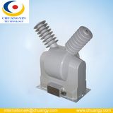
1. LV & MV epoxy resin CTs and PTs (0.66kV, 7.2kV, 11kV, 17.5kV, 24kV, 33kV, 72.5kV etc ) for switchgear or power system.
2. Cold shrink cable, Separable accessories(EPDM).
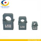
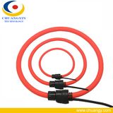
3. Split core Current Transformer, Clamp- on Current Transformer and Rogowski coil Current Transformeretc.
4. CTs and Relays for energy meter.
Passed KEMA, TYPE TEST REPORT, CE, TUV, ISO and RoHS standards
We have a head office in Shenzhen High-tech Park and two subsidiary production bases named Jiangxi Chuangyin (20, 000 square meters) and Zhuhai Chuangyin (10, 000 square meters). We offer a wide product range such as all kinds of current transformers from mini CT to medium voltage CT, and from solid core CT to split core CT. We are a key supplier of energy meter, switchgear and utility companies for more than 10 years. We are the only company who make current transformer and relay together, and provide good solution for smart meters. Our experienced engineers have good knowledge in energy meters and switchgears. Furthermore, we have certificates such as CE, RoHS and ISO from TUV.
Contact us today to know more.
Thank you for your attention and support. Chuang Yin will stay with you to create a better future.
www.chuangy.com