Disconnector Center Break Isolator and Double Break Isolator
| Price: |
Negotiable/Piece |
| Trade Terms: |
FOB,CFR,CIF |
| Min Order: |
1/Piece |
| Pay Type: |
L/C,T/T,D/P,Western Union |
| Prod Model: |
220kv |
| Markets: |
North America,South America,Eastern Europe,Southeast Asia,Africa,Oceania,Mid East,Eastern Asia,Western Europe |
| Type: |
High-voltage |
| Structure: |
Three-column Disconnector |
| Installation: |
Outdoor High-voltage |
| Operation: |
Manual |
| Grounding: |
Single Ground |
| Series: |
Three |
| Run: |
Turn the Horizontal |
| Switching Mode: |
Single Throw-in |
| Certification: |
CE |
| Brand: |
Ville |
Product Description
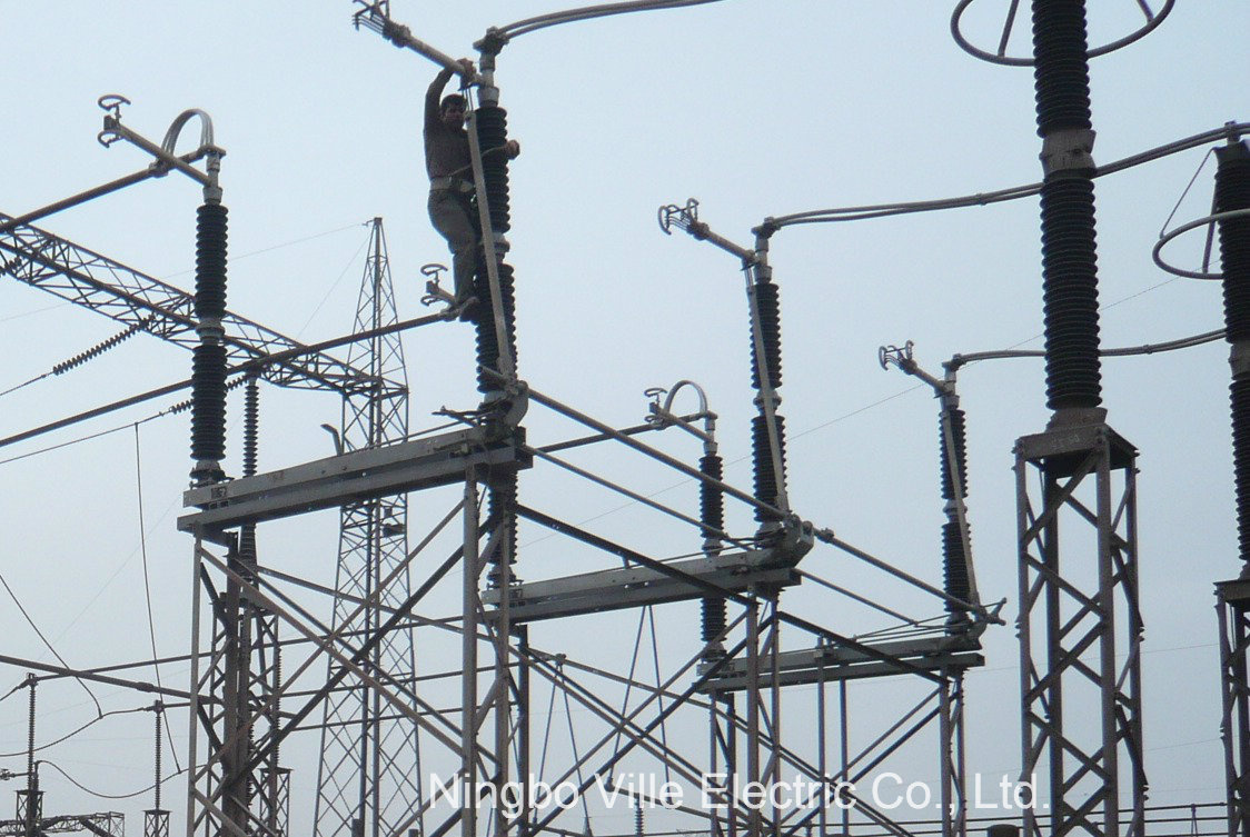
Disconnector for 220kV Substation
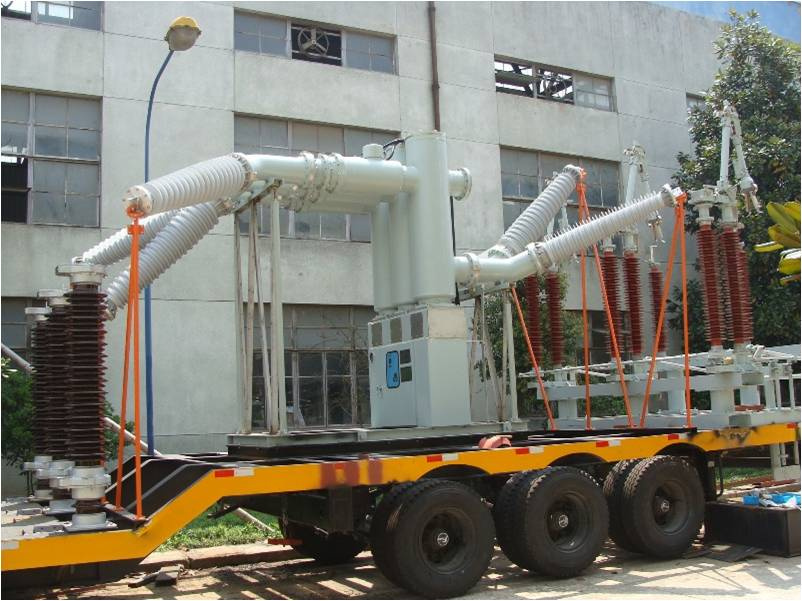
These disconnectors are , no load switching devices
which physically isolate the lines. They are designed for
horizontal outdoor application and can also be designed
for vertical installation. For earthing and closing of
switchyard portions of the installation, the earthing
switches are provided on disconnector. If required.
The following documents were referred to during the preparation of this specification. In case of conflict, the provisions of this specification shall take precedence.IEC 129:1975: Alternating Current Disconnectors (Isolators) and Earthing SwitchesIEC 60694:2002: Common Specifications for High Voltage Switchgear and ControlgearBS 729: Hot dip galvanized coating on iron and steel articlesIEC62271-102Isolator (Disconnector) - a mechanical switching device which provides, in the open position, an isolating distance in accordance with Electrical Safety requirements.SERVICE CONDITIONSThe isolator shall be suitable for continuous operation outdoors in tropical areas at altitudes of up to 2200m above sea level, humidities of up to 90%, average ambient temperature of +30ºC with a minimum of -1ºC and a maximum of +40ºC and heavy saline conditions along the coast.4.2. DESIGN AND CONSTRUCTION4.2.1 The Isolator, Solid Link shall be designed and constructed in accordance with IEC 129 and IEC 60694.4.2.2 The isolating link shall be of the vertical opening, designed for single phase manual operation. It shall be easily removed and replaced by using a portable operating rod.4.2.3 The isolating link shall incorporate double porcelain insulators to suit voltage requirements and mounted on hot dipped galvanised steel under base suitable for vertical mounting.4.2.4 The isolating link shall be arranged so that each unit is mounted independently on an angle bracket. It shall be supplied complete with the angle bracket and accessories suitable for mounting on 'U' type steel channel. The drawings to be submitted shall indicate all the applicable mounting positions.4.2.5 The isolator shall be designed such that in fully open position, it shall provide adequate electrical isolation between the contacts on each phase. It shall conform to the requirement as single point isolation for safety.4.2.6 All steel parts shall be hot dip galvanized to BS 729. The minimum coating of galvanizing required is 80 microns.4.2.7 The solid link shall be removable from the mounting by use of operating rod.4.2.8 All current carrying parts of the isolator shall be made of high conductivity material.4.2.9 The isolator shall be fitted with clamp connectors for Aluminium (ACSR) conductor of Aluminium (ACSR)conductor of up to 18.2mm diameter.The rating of the complete isolator shall be as follows: -Rated voltage36 kVRated frequency50 HzRated lightning impulse withstand voltage200 kVRated power frequency withstand voltage, dry95 kVRated normal current400 AmpsRated short time withstand current for 3 sec, min.18.0 kAMinimum creepage distance of insulators900 mm SOLID LINKS 11KV | N/O | DETAIL | | DATA |
| 1 | Description | | Solid link assembly complete with link
rated at 200A and mounting bracket to PIESA 002.(See Figure 1 to Figure 12 below) |
| 2 | System conditions of service
a) nominal Voltage (Un) r.m.s |
kV |
11 |
| b) maximum system voltage (Um) r.m.s | KV | 12 |
| c) earthing | | Effective & non effective |
| d) Frequency | Hz | 50 |
| 3 | Site conditions of service
a) altitude |
m |
1400 |
| b) Operating Ambient temperature | °C | -1 to 40 |
| c) Humidity | % | 85 |
| 4 | Rating | | |
| a) Nominal voltage | kV | 11 |
| b) Rated current | Solid link |
A |
200 |
Cut out base |
A |
200 |
| 5 | Electrical components | | |
| a) Insulator material specification | | Porcelain |
| Dielectric strength | | |
| Lightning impulse withstand (1.2/50) | kV | 95 |
Power frequency wet withstand voltage
r.m.s | kV | 28 |
| 6 | Specific creepage distance | mm/kV | 25 |
| 7 | General information to be provided
with bid:
Drawings and brochures showing outline and general arrangement |
Yes/No |
Yes |
| | b) Detailed drawings of all items
showing critical tolerances to be provided with bid | Yes/No | Yes |
| 8 | Previous Type test report/certificate on
complete solid link assembly to be provided with bid |
Yes/No |
Yes |
| 10 | Routine tests (acceptance tests on
sample
Product) to be provided on delivery | Yes/No | Yes |
| 11 | Applicable standard | | PIESA 002 |
| 12 | Other applicable standards | | NRS 035
SABS IEC 60282-2
SABS IEC 60186
BS 137 part 2 |
TRI-LINKS Lot 3-(a) 11kV with interrupters | N/O | DETAIL | | DATA |
| 1 | TYPE | | 11kV pre-assembled gang
operated overhead line load break switch complete with expulsioninterrupters |
| 2 | Mounting configuration | | Horizontal |
| 3 | Mode of operation | | Manually operated pole
mounted linking rod and handle withlocking facilities |
| | a) nominal Voltage (Un) r.m.s | kV | 11 |
| b) maximum voltage (Um) r.m.s | KV | 12 |
| c) earthing | | Effective & non effective |
| d) Frequency | Hz | 50 |
| e) rated current | Amp | 400 |
| f) Fault closing capacity | kA | 12.5 |
| 4 | Site conditions of service
a) altitude |
metres |
1400 |
| b) Operating Ambient temperature |
°C |
-1 to +40 |
| c) Relative humidity | % | 85 |
| 5 | Electrical components | | |
| a) Insulator material specification | | High Temperature Vulcanised
Silicon rubber |
| b) Cross arm and operating controls materials | | Hot dip galvanized steel to
SAN760 |
| Dielectric strength | | |
| Lightning impulse withstand (1.2/50) | kV | 95 |
| | Power frequency wet withstand voltage r.m.s | KV | 28 |
| | Short time current rating -1sec | kA | 12.5 |
| 6 | creepage distance | mm/kV | 25 |
| 7 | General information to be provided with bid:
Drawings and brochures showing
Outline and general arrangement |
Yes/No |
Yes |
| 8 | Previous Type test report/certificate on complete
assembly to be provided with bid | Yes/No | Yes. |
| 9 | Routine tests (acceptance tests on sample
Product) to be provided on delivery. | Yes/No | Yes |
| 10 | Applicable standards | | IEC62271 |
FURTHER REQUIREMENTS:
Water shall not be able to accumulate on any part of the equipment nor shall any feature introduce moisture into any component.
The design shall incorporate all reasonable precautions and provisions for the safety of personnel concerned with the operation and maintenance of the same.
The current path shall be such that load current shall only flow through high conductive materials such as copper and its alloys.Load current shall not be permitted to flow through ferrous components, springs, or spring-loaded mechanisms.
All load current paths shall be so designed that the relevant parts of the switch are capable of carrying the specified rated current without exceeding the permitted temperature rise.
SUPPLIMENTARY NOTES
Suppliers should give sufficient information including drawings (which must be brief, clear and to the point) on how their switch designs addresses these requirements. Further, Suppliers may offer better alternatives that are of cost benefits to customer, It istherefore imperative that schedule "B" is completed by the tenderer. Any deviations/modifications/alternatives specification must be listed in schedule "C.
33kV with interrupters | N/O | DETAIL | | DATA |
| 1 | TYPE | | 33kV pre-assembled gang
operated overhead line load break switch complete with expulsioninterrupters |
| 2 | Mounting configuration | | Horizontal |
| 3 | Mode of operation | | Manually operated pole
mounted linking rod and handle withlocking facilities |
| | a) nominal Voltage (Un) r.m.s | kV | 33 |
| b) maximum voltage (Um) r.m.s | KV | 36 |
| c) earthing | | Effective & non effective |
| d) Frequency | Hz | 50 |
| e) rated current | Amp | 200 |
| f) Fault closing capacity | kA | 12.5 |
| 4 | Site conditions of service
a) altitude |
metres |
1400 |
| b) Operating Ambient temperature |
°C |
-1 to +40 |
| c) Relative humidity | % | 85 |
| 5 | Electrical components | | |
| a) Insulator material specification | | High Temperature Vulcanised
Silicon rubber |
| b) Cross arm and operating controls materials | | Hot dip galvanized steel to
SAN760 |
| Dielectric strength | | |
| Lightning impulse withstand (1.2/50) | kV | 170 |
| Power frequency wet withstand voltage r.m.s | KV | 70 |
| | Short time current rating -1sec | kA | 12.5 |
| 6 | creepage distance | mm/kV | 25 |
| 7 | General information to be provided with bid: | | |
| | Drawings and brochures showing
Outline and general arrangement |
Yes/No |
Yes |
| 8 | Previous Type test report/certificate on complete
assembly to be provided with bid | Yes/No | Yes |
| 9 | Routine tests (acceptance tests on sample
Product) to be provided on delivery | Yes/No | Yes |
| 10 | Applicable standards | | IEC62271 |
FURTHER REQUIREMENTS:
Water shall not be able to accumulate on any part of the equipment nor shall any feature introduce moisture into any component.
The design shall incorporate all reasonable precautions and provisions for the safety of personnel concerned with the operation and maintenance of the same.
The current path shall be such that load current shall only flow through high conductive materials such as copper and its alloys.Load current shall not be permitted to flow through ferrous components, springs, or spring-loaded mechanisms.
All load current paths shall be so designed that the relevant parts of the switch are capable of carrying the specified rated current without exceeding the permitted temperature rise.
SUPPLIMENTARY NOTES
Suppliers should give sufficient information including drawings (which must be brief, clear and to the point) on how their switch designs addresses these requirements. Further, Suppliers may offer better alternatives that are of cost benefits to custoemr.
11kV without interrupters | N/O | DETAIL | | DATA |
| 1 | TYPE | | 11kV pre-assembled gang
operated overhead line switch withoutexpulsion interrupters (non-load breakswitch) |
| 2 | Mounting configuration | | Horizontal |
| 3 | Mode of operation | | Manually operated pole
mounted linking rod and handle withlocking facilities |
| | a) nominal Voltage (Un) r.m.s | kV | 11 |
| b) maximum voltage (Um) r.m.s | KV | 12 |
| c) earthing | | Effective & non effective |
| d) Frequency | Hz | 50 |
| e) rated current | Amp | 400 |
| 4 | Site conditions of service
a) altitude |
metres |
1400 |
| b) Operating Ambient temperature |
°C |
-1 to +40 |
| c) Relative humidity | % | 85 |
| 5 | Electrical components | | |
| a) Insulator material specification | | High Temperature Vulcanised
Silicon rubber |
| b) Cross arm and operating controls materials | | Hot dip galvanized steel to
SAN760 |
| Dielectric strength | | |
| Lightning impulse withstand (1.2/50) | kV | 95 |
| Power frequency wet withstand voltage r.m.s | KV | 28 |
| | Short time current rating -1sec | kA | 12.5 |
| 6 | creepage distance | mm/kV | 25 |
| 7 | General information to be provided with bid: | | |
| | Drawing and brochures showing
Outline and general arrangement |
Yes/No |
Yes |
| 8 | Previous Type test report/certificate on complete
assembly to be provided with bid | Yes/No | Yes |
| 9 | Routine tests (acceptance tests on sample
Product) to be provided on delivery | Yes/No | Yes |
| 10 | Applicable standards | | IEC62271 |
FURTHER REQUIREMENTS:
Water shall not be able to accumulate on any part of the equipment nor shall any feature introduce moisture into any component.
The design shall incorporate all reasonable precautions and provisions for the safety of personnel concerned with the operation and maintenance of the same.
The current path shall be such that load current shall only flow through high conductive materials such as copper and its alloys.Load current shall not be permitted to flow through ferrous components, springs, or spring-loaded mechanisms.
All load current paths shall be so designed that the relevant parts of the switch are capable of carrying the specified rated current without exceeding the permitted temperature rise.
SUPPLIMENTARY NOTES
Suppliers should give sufficient information including drawings (which must be brief, clear and to the point) on how their switch designs addresses these requirements. Further, Suppliers may offer better alternatives that are of cost benefits to
33kV without interrupters | N/O | DETAIL | | DATA |
| 1 | TYPE | | 33kV pre-assembled gang
operated overhead line switch withoutexpulsion interrupters (non-load breakswitch) |
| 2 | Mounting configuration | | Horizontal |
| 3 | Mode of operation | | Manually operated pole
mounted linking rod and handle withlocking facilities |
| | a) nominal Voltage (Un) r.m.s | kV | 33 |
| b) maximum voltage (Um) r.m.s | KV | 36 |
| c) earthing | | Effective & non effective |
| d) Frequency | Hz | 50 |
| e) rated current | Amp | 200 |
| 4 | Site conditions of service
a) altitude |
metres |
1400 |
| b) Operating Ambient temperature |
°C |
-1 to +40 |
| c) Relative humidity | % | 85 |
| 5 | Electrical components | | |
| a) Insulator material specification | | High Temperature Vulcanised
Silicon rubber |
| b) Cross arm and operating controls materials | | Hot dip galvanized steel to
SAN760 |
| Dielectric strength | | |
| Lightning impulse withstand (1.2/50) | kV | 170 |
| Power frequency wet withstand voltage r.m.s | KV | 70 |
| | Short time current rating -1sec | kA | 12.5 |
| 6 | creepage distance | mm/kV | 25 |
| 7 | General information to be provided with bid: | | |
| | Drawing and brochures showing
Outline and general arrangement |
Yes/No |
Yes |
| 8 | Previous Type test report/certificate on complete
assembly to be provided with bid | Yes/No | Yes |
| 9 | Routine tests (acceptance tests on sample
Product) to be provided on delivery | Yes/No | Yes |
| 10 | Applicable standards | | IEC62271 |
FURTHER REQUIREMENTS: Water shall not be able to accumulate on any part of the equipment nor shall any feature introduce moisture into any component.The design shall incorporate all reasonable precautions and provisions for the safety of personnel concerned with the operation and maintenance of the same.The current path shall be such that load current shall only flow through high conductive materials such as copper and its alloys.Load current shall not be permitted to flow through ferrous components, springs, or spring-loaded mechanisms.All load current paths shall be so designed that the relevant parts of the switch are capable of carrying the specified rated current without exceeding the permitted temperature rise. SUPPLIMENTARY NOTES Suppliers should give sufficient information including drawings (which must be brief, clear and to the point) on how their switch designs addresses these requirements. Further, Suppliers may offer better alternatives that are of cost benefits to.
Ningbo Ville Electric Co., Ltd. One of wholly owned subsidiaries of VILLE INDUSTRY, It was invested by VILLE INDUSTRY, It is a well-know listed company in China specialized in R&D of electric power technology, equipment manufacturing and engineering services specialized in research, development, production of transformer and high voltage & low voltage electrical power equipment
Our Transmission and distribution companies can provide with whole solution for transformer substation and switch substation trunkey project!
The rated voltage from 11kV up to 132kV.
It locates in Hi-technical enterprise R & D center zone of Ningbo, Zhejiang province, which is one of the well-know coastal city in China. Its professional engaged in power substation, power plant project and electrical power complete equipments.
Working field: Manufacturing, engineering, designing, executing and commissioning for HV and LV electrical products. Turnkey substation from 11KV to 132KV.
Our transformer factory main working is visiting end user's site do measure and reseach before designe, and providing economic transformer solution for customer. Engineering, manufacturing, executing, commissioning and repairing for different kind of transformer (04kv -500kv ).
The products are mainly used in Steel plant; Power - Fossil fuel plant, Nuclear power plant, Railway, Subway and Airport. Wind power generation; Hydroelectric plant engineering; International power generation plant; Power substation transmission and distribution; Residential housing estate power distribution system and so on.
Transformer factory Product includes:
Three phase double (three)- winding power transformer, generator power transformer, auto power transformer, rectifier transformer for each industry, furnace transformer, movable transformer, traction transformer and reactor, power plant auxiliary and standby transformers, transformers for substations of backbone and distribution networks. Transformer for metallurgical companies etc.
In order to achieve the enterprise's strategic target---being stronger, larger, and superior, we continue to expand throughout the world's markets for power transmission and distribution area. And we also actively attach our team to competition, walking forward to the mission of "First-class worldwide transformer supplier"
Supply the guide drawings and installation manuals information directions on the method of handling, storage, mounting and erection of transformers.
Power equipment application:
Power-fossil fuel plant, Steel plant, Infrastructure- railway, international generation, substation, hydropower station, wind power substation, transmission and distribution.
We has excellent experience and good capacity in complete projects equipments in Generation, Substation, Transmission and Distribution from 400V-330kv, especially in Power plant, Substation construction and Transmission line, including of design, complete equipment, installation, Commissioningand after-sales service, and also design the complete Electrical Solutions according to customer's demand. We are mainly services to International State Power Board, Power Construction Contractor, Power Project Contractor, Factories and the Electric Power Project in the world.
In order to achieve the enterprise's strategic target---being stronger, larger, and superior, we continue to expand throughout the world's markets for power transmission and distribution area. And we also actively attach our team to competition, walking forward to the mission of "First-class worldwide electrical equipment supplier
More >
Other Products with This Manufacturers