| Prod Model: |
SXGN2-10 |
| Rated Frequency: |
50/60Hz |
| Rated Current: |
630A, 1000A,1250A,2000A, 2500A,3150A |
| Rated Voltage: |
10 Kv |
| Protection Grade: |
IP2X |
| Operation Mode: |
Electromagnetic, Spring Energy Storage Type |
| Mechanical Life: |
10000 Times |
| Arcing Time: |
< 20 Ms |
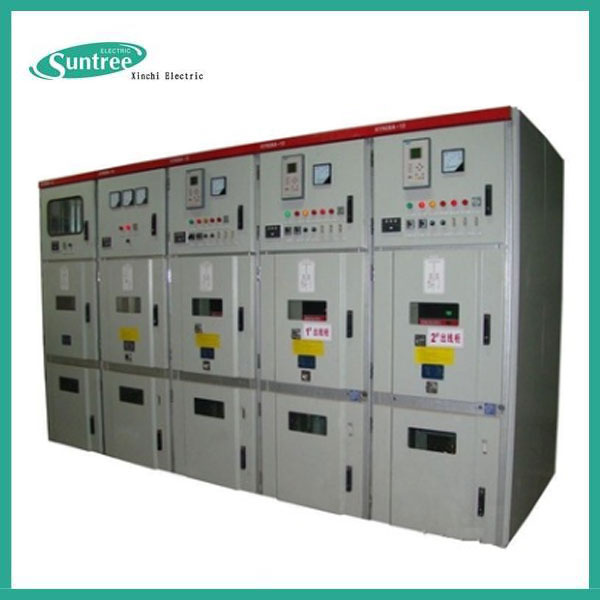
Product Description
SXGN2-10 Box Type Fixed Meta-Enclosed Switchgear with High Quality and High Voltage
1.1 SXGN2-10 box type fixed metal-enclosed switchgear (hereinafter referred to as switchgear) is mainly used for power receiving and distribution in AC 50Hz system of three phase and 12KV or below, it's especially suitable for place in need of frequent operation, it's a single bus-bar system, single bus-bar with bypath and double bus-bar structure are also available.
1.2 SXGN2-10 (G) box type fixed AC metal-enclosed switchgear is a plateau type product developed for high altitude area on the basis of general switch.
1.3 This switchgear complies with requirement of national standard GB3906 3~35kV AC Metal-Enclosed Switchgear and international standard IEC 298, it also owns "five-protection" locking function.
1.4 ZN28A-10 series vacuum circuit breaker and SN10-10type oil-minimum circuit breaker equipped with CD10, CD17 series electromagnetic type and CT8 series as well as CT17/19 series spring operation mechanism are sued as main switch of this switchgear, the user can also adopt ZN28-10, ZN73 integrated type circuit breaker, GN30-10 rotary disconnecting switch, GN22-10 high current disconnecting switch and GN30-10 rotary high current disconnecting switch according to requirement.
| 2. Normal Application Condition |
2.1 Ambient temperature: -5?~+40?;
2.2 Altitude: ?1000m; altitude of plateau type switchgear shall not be more than 3000m;
2.3 Relative humidity: Daily average value not more than 95%, monthly average value nor more than 90%;
2.4 Water vapor pressure: Daily average value not more than 2.2 x 10 -3 Mpa, monthly average value not more than 1.8 x 10 -3 Mpa;
2.5 Shake intensity: not more than 8 degree.
2.6 In place where is free from fire and explosion danger, severe pollution, chemical corrosion and intense shake.
Technical Data of Switchgear
| No. | Item | Unit | Technical Data |
| 1 | Rated voltage | KV | 10 |
| 2 | Rated operate voltage | KV | 12 |
| 3 | Rated current | A | 630 | 1000 | 1000 | 1250 | 2000 | 2500 | 3150 |
| 4 | Rated short circuit breaking current | KA | 20 | 31.5 | 40 |
| 5 | Rated short time withstand current(4S) | KA | 20 | 31.5 | 40 |
| 6 | Rated peak withstand current | KA | 50 | 80 | 100 |
| 7 | Rated short circuit closing current (peak value) | KA | 50 | 80 | 100 |
| 8 | Protection grade | | IP2X |
| 9 | Operation mode | | Electromagentic,spring energy storage type |
| 10 | Outline size (width*depth*height) | mm | 1100*1200*2650(below 1250A) |
* Rated current of plateau type switchgear is 630/1000/1250A.
* The outline size of plateau type switchgear is 1200 x 1350 x 2900mm.
It's a mental-enclosed box type structure, the framework of cabinet body is welded by angle steel, the inner cabinet is divided into circuit breaker room, bus room and relay room, the upper relay room can be designed into miniature bus room. The rooms are separated with steel plate to each other.
The circuit breaker room is at the bottom of cabinet, the drive mechanism of circuit breaker is connected with operation mechanism by pull rod, the upper connection terminal of circuit breaker is connected with current transformer, and the current transformer is connected with connection terminal of lower disconnecting switch, the upper connection terminal of circuit breaker is connected with connection terminal of upper disconnecting switch, there's a pressure relief passage set in circuit breaker room, if there's arc inside, the pressure can be released through the exhaust passage.
The bus room is at the back of upper cabinet, in order to reduce the cabinet height, the bus-bar is arranged with shape, with porcelain insulator of 7350 N bending strength as the support, the bus is connected with connection terminal of upper disconnecting switch.
The cable room is at the back of lower cabinet, monitoring device can be set to the support insulator in the cable room, the cable is fixed on the
supporting frame. When the main connection is made as interconnection scheme, this room will be bus-tie room.
The operation mechanism of circuit breaker is in the left front, and the operation and interlocking mechanism of disconnecting switch are on
the top of it.
There are two sides for maintenance, front side is maintenance for secondary element of relay room, maintenance for operation mechanism, mechanism interlocking and drive part as well as maintenance for circuit breaker, and the back side is for maintenance of main bus-bar and cable terminal, there are illuminating lamps both in circuit breaker and cable room.
There is earthed copper bus-bar set at the bottom of front door parallel to width direction of cabinet, with section area of 4 x 40mm2.
Mechanical interlocking: in order to prevent the disconnected from switching on or off on load, prevent misoperation of circuit breaker switching on or off; prevent people from entering charged room, prevent the earth switch from switching on in charged condition and prevent earthed blade from switching on in charged condition. Corresponding mechanical interlocking is used for the switchgear, see the followings for operation procedure of mechanical interlocking:
3.1 Power off operation (operation - maintenance)
When the switchgear is in operation position, namely, the upper and lower disconnecting switch, circuit breaker is in switching on condition, the
front and back door are closed, well locked and is in the charged operation, the small handle is in the operation position on this moment. The
power off shall be performed according to the following order:
1) Switch off the circuit breaker;
2) Turn the small handle to "switch off and lock" position, the circuit breaker can be switched on;
3) Insert the operating handle into the operation hole of lower disconnecting switch, pull it from top to
bottom till to the switching off position of lower disconnecting switch;
4) Insert the handle into operation hole of upper disconnecting switch, and pull it from top to bottom until to the switching off position of upper disconnecting switch;
5) Take down the handle, insert it into operating hole of earth switch, and pull it from bottom to top until the earth switch is in switching on position;
6) Turn the small handle to "maintenance"position, then first open the front door, take out key to program lock to open the back door, power off operation finishes. The maintenance personnel can do maintenance and repair to circuit breaker and cable room.
3.2 Power sending operation (maintenance - operation)
1) Close the back door and lock it well;
2) Take out the key and close the front door;
3) Turn the small handle from maintenance position to switching off and lock position, then the front door is locked on this moment;
4) The circuit breaker can't be switched on, insert the operation handle to operating hole of earth switch, pull it from the bottom to top to make the earth switch in the switching off position;
5) Take the operation handle down and insert it into operating hole of disconnecting switch, pull it from the bottom to top until the upper disconnecting switch is in the switching on position;
6) Take the operation handle down, insert it into the operating hole of lower disconnecting switch, pull it from bottom to top to make the lower disconnecting switch in the switching on position;
7) Take the operation handle out and turn the small handle to operation position, then the circuit breaker can be switched on.
| 4. Installation, Adjustment & Maintenance |
4.1 The upward and downward dynamic load produced during switching on of vacuum circuit breaker is about 7840N, this data is used for
foundation stress estimation during foundation design.
4.2 Foundation
See figure 2 for reference of design and construction of switchgear foundation, the foundation shall be flat and neat.
4.3 Installation procedure and attentions
a) Put the switchgear on the foundation according to arrangement order, adjust straightness, verticality, degree of level of packed switchgear
into good condition, then firmly fix the switchgear to basic channel steel with M12 bolt or way of spot welding.
b) Connect the cabinets with M12 x 30bolt.
c) Install the main bus-bar, open the top cover board of bus room for installation, fasten the cover board after installation, the contact surface
shall be flat, neat without pollution during bus-bar connection, any pollution found shall be cleaned, the surface shall be coated with neutral
vaseline.
d) Install the primary cable, after the cable head is made, fix it on the supporting frame, the contact surface of cable and bus-bar shall be flat
and neat, the surface shall be coated with neural vaseline, after that, connect the cable and make it firm, and separating board shall be used
to insulate cable room and cable channel after construction of cable.
e) Connect the bus-bar of the cabinets into one whole along the arrangement direction of switchgear, check whether there's any missing for
operation and protection earth, whether the earth circuit is conductive continuously, the operation earth resistance shall not be more than 1000
μΩ, and the protection earth resistance shall not be more than 4μΩ.
f) Install the secondary circuit cable, put the cable through the left side of mechanism and enter the relay room along the side wall, tap it to
corresponding terminal block, please pay attention to cable code during construction, avoid missing or incorrect connection of terminals, don't
forget to seal the cable holes after the construction finishes.
4.4 Acceptance check and preparation before putting into running
4.4.1 Acceptance check item
a) Check whether the model and specification of electric element installed in the switchgear are in conformity with order data.
b) Check whether there's any loose fastening piece and fasten the loose one.
c) Check the connection point of bus-bar, whether the contact is firm, repair it if poor contact is found.
d) Manually operate the disconnecting switch, circuit breaker and mechanical interlocking procedure for 3-5 times, it shall be fast without
blocking, and the operation shall be correct and the procedure shall be no error.
e) Check whether the mechanical characteristic of circuit breaker and disconnecting switch are in conformity with their own requirement.
f) Check whether the secondary connection complies with drawing requirement, do an operation test to the switching on of secondary circuit
in the condition that the main circuit isn't switched on, and the result shall comply with requirement of secondary connection diagram.
g) For the resistance measurement of main circuit, there are many switchgear schemes, so the resistance value of each phase has not been
determined, the provisional measurement position is circuit breaker and the electric lapping position, the resistance shall not exceed regulated
value, and that of electric lapping position shall not be more than μΩ, DC voltage drop is used as the way to measure the voltage drop with
100A DC current.
h) Make a insulation strength test for the main circuit, apply an AC 50Hz voltage of 200V between the conductor and shell for 1 min, there shall
be disruptive discharge, there is electric element part in secondary circuit, and the test voltage can be determined to manufacturer and user.
i) Make a power frequency insulation voltage test in main circuit, apply an AC 50Hz voltage (85% of the regulated voltage in GB311.1-6
according to rated voltage of switchgear) between the phase and earth as well as phases for 1 min, there shall be no flashover phenomenon.
When the plateau type switchgear is tested in altitude less than 1000m, the test voltage shall be the result of rated withstand voltage regulated
in clause 3.4 of GB311.1 multiplied by altitude correction factor Ka.
4.4.2 Preparation before the product is put into running.
a) Lubricating oil shall be injected in moving part.
b) Switch on the power supply like control, signal and lighting.
c) When the disconnecting switch and circuit breaker are in switching off condition, transmit the power to the main bus-bar, that is to switch on
the inlet circuit breaker cabinet.
d) Switch on the disconnecting switch of switchgear with voltage transformer, check whether the voltmeter is correct or not, and continue if
there's no error.
e) Switch on the arrester, disconnecting switch of station transformer and related auxiliary electric apparatus to put them into running.
f) Switch on the circuit breaker of feeder cabinet one by one, check whether the ammeter is right condition.
4.5 Maintenance and repair
4.5.1 After the switchgear is put into running, do monitoring and maintenance as the following.
a) Observe the main bus-bar and bus-bar at electric connection joint, repair shall be taken if the colour of bus-bar is found changed due to
overheat.
b) Observe whether the power supply of lighting, control and signal is normal.
c) Record the operation times of circuit breaker.
4.5.2 Repair
The repair for switchgear includes fault repair and regular repair, fault repair is to prevent the fault operation and accident enlargement, if
there's any accident happening or being about to happen, repair shall be taken to fault position to eliminate the fault. The regular repair is to do
the repair at regular intervals according to operation regulation, the repair content has been shown as followings:
a) Clean the dust of each part especially the dust on insulation surface.
b) Check the program lock and mechanical interlock to keep reliable and fast work and correct procedure.
c) Make the maintenance and repair as well as debugging according to regulation of circuit breaker, disconnecting switch, operation mecha-
nism etc.
d) Check whether all the contact positions of apparatus have good contact, check the earth circuit to keep it continuous conduction.
e) Fasten all the screws and pins.
4.6 Operation, acceptance and storage
4.6.1 The product can be packed and delivered only after qualification test before leaving factory. During package, the product shall be
fastened on the bottom block with bolt, and during delivery, only vertical rotation is allowed, upside down placement, overturn, tumble and
falling are not allowed.
4.6.2 Make an acceptance according to packing list, the whole product as well as its accessories.
4.6.3 Storage
Before installation, the product shall be stored in the warehouse, it can't be in rain or affected by damp when it's not stored in the
warehouse, the electric element and component can't be disassembled at will.
5.1 Certificate of quality;
5.2 Operation instruction;
5.3 Secondary construction wiring diagram;
| 6. Wearing part, Accessory & Spare Part |
6.1 Wearing part of circuit breaker and other electric apparatus;
6.2 Wearing part of switchgear shall be negotiated by user and manufacturer;
6.3 Accessory and spare part of switchgear, the user can order with manufacturer.
| 7. Notes for Placing Order |
7.1 The buyer shall offer the main connection scheme number as well as signal line system diagram and arrangement diagram.
7.2 Secondary circuit connection schematic diagram and terminal arrangement diagram shall be offered by buyer, if there's no terminal
arrangement diagram offered, it shall be supplied according to regulation of manufacturer.
7.3 Model, specification and quantity of electric element inside of switchgear.
7.4 The material and specification of main and branch bus-bar, it will be supplied according to regulation of manufacturer if they are not offered.
7.5 The buyer shall notify the manufacturer during order placing if the switchgear is used in special environment.
7.6 The buyer shall notify the manufacturer the type and quantity of accessory and spare part required.
Xinchi Electric Co., Ltd. is the best one, which stands out above the rest in China intelligent low voltage electrical field, meanwhile it is a grouping company in the "city of electrical".There are four branch companies subordinate to it:Yueqing Xinchi Electric Sci-Tech Co., Ltd, Yueqing Imp&Exp Co., Ltd, HK Yangming Electrical Technology Co., Ltd and Wenzhou Litto smart Co., Ltd.Moreover.There are 320 workers, the annual output value breakthrough one hundred million, and the export value arrive at ten million.
We always pay attention to manufacture and sell automatic industrial and control system, modular intelligent electrical equipments, such as circuit breakers, residual circuit breakers, contactors, isolators, solid state relay, control and protect switch, automatic transfer switch, electrical fire detecting system, surger protect device, multifunctional meter and new energy system fittings etc.
Especially DC circuit breaker, DC isolating switch, DC fuse, busbar chamber, waterproof switch and other products with leading technical level in this field...We are the first domestic company with CE, CB, IEC, Nemko, SAA, TUV, ISI and CCC certification.Our products are widely used by domestic famous enterprises, and it has become a OEM partner of many international famous brands.
We have fully implement the IS09001:2008 quality management system.It adopts advanced production equipment and precision detecting equipment, introduces high-tech process and high technology talents to provides powerful guarantee for product development, quality upgrading and management innovation of the company.
In order to seek after the excellence, Xinchi will continue to carry on the spirit of "practice, honesty, innovation, active", insist on the policy of " technology promotes industry, Brand promotes industrial", and we believe in "Technology innovation, famous in the world", working hard to let"XINCHI electric brand"walk towards to the world.