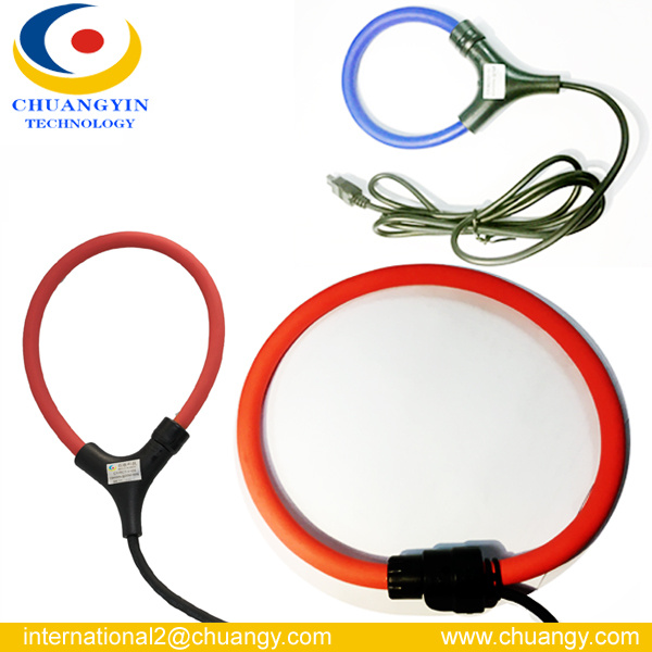
Series Clamp-on Flexible Rogowski Coil Current Transformers CY-RCTD03
The"RCTD03 lamp Clamp-on Flexible Rogowski coil current transformer" is designed for easy installed in tight spaces and without the need for dismantling the primary busbar or cables. It includes a flexible Rogowski coil probe and electronic modules with a display . The signal from the coil probe can be amplified by the electronic modules through the integration processing .The output signal can be directly used in oscilloscope, digital multimeter or data logger recording instrument. Feature: .Display LCD measured parameters.Flexible and light weights appearance.Easy & quick installation in tight spaces.Excellent linearity.Maximum measuring current up to 130A Applicaition:.Power quality monitoring .Power instrument meter.Smart logger.Energy sub-meters.Distributed measurement systems Model Code: General data:.Ambient operating temp:-10ºC-60 ºC(14-140 ºF). Ambient storage temp:-25ºC-75 ºC(13-167 ºF).Operating environment: Indoor , altitude up to 2000 meters.Standards Safety:IE 61010-1:2001,300V CAT Dimension: | Dimension (mm) | CY-RCTD03-120 | CY-RCTD03-190 | CY-RCTD03-305 |
| Window A | 120 | 190 | 305 |
| Coil OD B | 144 | 214 | 329 |
| Coil Length C | 400 | 600 | 1000 |
| Output connection | Standard BNC male head |
Electrical ParameterThe test environment for the accuracy:23±5ºC(73±9ºC), ≤85%RH Model
Data | CY-RCTD03-120 | CY-RCTD03-190 | CY-RCTD03-305 |
| Current Range | 10A-30kA |
| Frequency | 25Hz-20kHz |
Output
Voltage | Rated Current | 1000A
2000A | 2000A
3000A | 5000A
6000A |
| 50Hz | 1Mv/A@ Ipn=1000...3000A(0.5mV/A@Ipn=4000...6000A) |
| Maximum output | 3.0 V AC max (customizable) |
| Accuracy | ±1%(10%-100%In)@45-65Hz |
| Phase error | ±1%(10%-100%In)@45-65Hz, ±10º@20kHz |
| Linearity | ±0.2%(10%-100%In) |
| Position Sensitivity | ±1.0%(90º-270º), ±2%(0,45º,315º) |
| External Influence | ±1%Range (from the coil>200mm) |
| Noise | 8m V rms (60A)2m V rms (600/6000A) |
| Temperature Coefficient | ±0.08%/Cof the reading data |
| Friquency Range | 10Hz TO 20kHz (-3DB) |
| Load Impedance | Mininum 100KΩ |
| Power | 4*AA /MN 1500//LR6 Battery(Eternal Adapter :9-12V DC) |
| Operating Voltage | 600V AC RMS or DC |
| Security Level | IEC61010-1:2001,600V CAT |
| Cable Length | 3m (measuring head to the electronics module) |
| Output terminals | BNC |
| Weight | 230g(measuring head),130g(Electronic modules) |
Usage Instruciton:
Note:Please browse our website and download product catalogue for detailed information. SHENZHEN CHUANGYIN TECHNOLOGY CO., LTD. ( CY Group )Certification: KEMA, ISO9001, UL, SGS, CE.( Your reliable partner for CT,PT (up to 72.5KV) ,Cable accessories, Split core CT, Rogowski Coil , Latching Relay, Flx-core CT )Address: 1st Floor, Building B, Jiada R&D Building, No.5 Songpingshan Rd., Shenzhen High-Tech Zones, Nanshan, Shenzhen, China, Post code: 518057Tel: +86 0755-86000716/ 86007806Fax: +86 0755-86000614Web: www.chuangy.comRogowski coil Arvin Q.Business Development Executive A Rogowski coil, named after Walter Rogowski, is an electrical device for measuring alternating current (AC) or high speed current pulses. It consists of a helical coil of wire with the lead from one end returning through the centre of the coil to the other end, so that both terminals are at the same end of the coil. The whole assembly is then wrapped around the straight conductor whose current is to be measured. There is no metal (iron) core. The winding density, the diameter of the coil and the rigidity of the winding are critical for preserving immunity to external fields and low sensitivity to the positioning of the measured conductor.[1][2]
Since the voltage that is induced in the coil is proportional to the rate of change (derivative) of current in the straight conductor, the output of the Rogowski coil is usually connected to an electrical (or electronic) integrator circuit to provide an output signal that is proportional to the current. Single-chip signal processors with built-in analog to digital converters are often used for this purpose.[1]
Contents
[hide] - 1Advantages
- 2Disadvantages
- 3Applications
- 4Formulae
- 5Similar devices
- 6See also
- 7References
- 8External links
Advantages[edit]
This type of coil has advantages over other types of current transformers.
- It is not a closed loop, because the second terminal is passed back through the center of the toroid core (commonly a plastic or rubber tube) and connected along the first terminal. This allows the coil to be open-ended and flexible, allowing it to be wrapped around a live conductor without disturbing it. However, positioning of the measured conductor is important in that case: It has been shown that, with flexible sensors, the effect of the position on the accuracy ranges from 1 to 3%. Another technique uses two rigid winding halves with a precise locking mechanism.[2]
- Due to its low inductance, it can respond to fast-changing currents, down to several nanoseconds.[3]
- Because it has no iron core to saturate, it is highly linear even when subjected to large currents, such as those used in electric power transmission, welding, or pulsed power applications.[3] This linearity also enables a high-current Rogowski coil to be calibrated using much smaller reference currents.[1]
- No danger of opening the secondary winding.[3]
- Lower construction costs.[3]
- Temperature compensation is simple.[1]
- Conventional current transformers require an increase of the number of secondary turns, in order to keep the output current constant. Therefore, a Rogowski coil for large current is smaller than an equivalent rating current transformer.[4]
Disadvantages[edit]
This type of coil also has some disadvantages over other types of current transformers.
- The output of the coil must be passed through an integrator circuit to obtain the current waveform. The integrator circuit requires power, typically 3 to 24Vdc, while many commercial sensors use batteries to power their electronic parts.[5]
- Traditional split-core current transformers do not require integrator circuits. The integrator is lossy, so the Rogowski coil does not have a response down to DC; neither does a conventional current transformer (see Néel effect coils for DC). However, they can measure very slow changing currents with frequency components down to 1 Hz and less.[2]
Applications[edit]
Rogowski coils are used for current monitoring in precision welding systems, arc melting furnaces, or electromagnetic launchers. They are also used in short-circuit testing of electric generators and as sensors in protection systems of electrical plants. Another field of usage is the measurement of harmonic current content, due to their high linearity.[5]
Formulae[edit]
Example waveform of R.C. output for
switched-mode load. As explained above the output waveform - CH4 (green) - represents the
derivative
of the current waveform - CH2 (Blue). CH1 (Yellow) is 230V AC Mains waveform
The voltage produced by a Rogowski coil is
{\displaystyle v(t)={\frac {-AN\mu _{0}}{l}}{\frac {dI(t)}{dt}}},
where
- {\displaystyle A=\pi r^{2}} is the area of one of the small loops,
- {\displaystyle N} is the number of turns,
- {\displaystyle l=2\pi R} is the length of the winding (the circumference of the ring),
- {\displaystyle {\frac {dI(t)}{dt}}} is the rate of change of the current threading the loop,
- {\displaystyle \mu _{0}=4\pi \times 10^{-7}} V·s/(A·m) is the magnetic constant, and
- {\displaystyle R} is the major radius of the toroid, and
- {\displaystyle r} is its minor radius.
This formula assumes the turns are evenly spaced and that these turns are small relative to the radius of the coil itself.
The output of the Rogowski coil is proportional to the derivative of the wire's current. The output is often integrated so the output is proportional to the wire's current:
{\displaystyle V_{\rm {out}}=\int vdt={\frac {-AN\mu _{0}}{l}}I(t)+C_{\rm {integration}}}In practice, an instrument will use a lossy-integrator with a time constant much less than the lowest frequency of interest. The lossy integrator will reduce the effects of offset voltages and set the contant of integration to zero.
At high frequencies, the Rogowski coil's inductance will decrease its output.
The inductance of a toroid is
{\displaystyle L=\mu _{0}N^{2}(R-{\sqrt {R^{2}-a^{2}}})}
Similar devices[edit]
A device similar to the Rogowski coil was described by Arthur Prince Chattock of Bristol University in 1887.[6] Chattock used it to measure magnetic fields rather than currents. The definitive description was given by Walter Rogowski and W. Steinhaus in 1912.[7]
More recently, low-cost current sensors based on the principle of a Rogowski coil have been developed.[8] These sensors share the principles of a Rogowski coil, measuring the rate of change of current using a transformer with no magnetic core. The difference from the traditional Rogowski coil is that the sensor can be manufactured using a planar coil rather than a toroidal coil. In order to reject the influence of conductors outside the sensor's measurement region, these planar Rogowski current sensors use a concentric coil geometry instead of a toroidal geometry to limit the response to external fields. The main advantage of the planar Rogowski current sensor is that the coil winding precision that is a requirement for accuracy can be achieved using low-cost printed circuit board manufacturing.
See also[edit]
- Current
- Current transformer
- List of electronics topics
- Pulsed power
- Toroidal inductors and transformers
References[edit]
- ^ Jump up to:a b c d John G. Webster, Halit Eren (ed.), Measurement, Instrumentation, and Sensors Handbook, Second Edition: Electromagnetic, Optical, Radiation, Chemical, and Biomedical Measurement, CRC Press, 2014, ISBN 1-439-84891-2, pp. 16-6 to 16-7.
- ^ Jump up to:a b c Klaus Schon, High Impulse Voltage and Current Measurement Techniques: Fundamentals - Measuring Instruments - Measuring Methods, Springer Science & Business Media, 2013, ISBN 3-319-00378-X, p. 193.
- ^ Jump up to:a b c d Slawomir Tumanski, Handbook of Magnetic Measurements, CRC Press, 2011, ISBN 1-439-82952-7, p. 175.
- Jump up^ Stephen A. Dyer, Wiley Survey of Instrumentation and Measurement, John Wiley & Sons, 2004, ISBN 0-471-22165-1, p. 265.
- ^ Jump up to:a b Krzysztof Iniewski, Smart Sensors for Industrial Applications, CRC Press, 2013, ISBN 1-466-56810-0, p. 346.
- Jump up^ "On a magnetic potentiometer", Philosophical Magazine and Journal of Science, vol. XXIV, no. 5th Series, pp. 94-96, Jul-Dec 1887
- Jump up^ Walter Rogowski and W. Steinhaus in "Die Messung der magnetischen Spannung", Archiv für Elektrotechnik, 1912, 1, Pt.4, pp. 141-150.
- Jump up^ Patent for a planar Rogowski current sensor U.S. Patent 6,414,475, granted 2 Jul 2002.