| No. | DESCRIPTION TION | UNID. | VALUE REQUIRED | VALUE OFFERED |
| | | | | |
| 1.0.0 | GENERAL DATA | | | |
| 1.1.0 | Maker | | | ABB/SAC |
| 1.2.0 | Model | | | RET650 |
| 1.3.0 | Country of manufacture | | | Sweden/China |
| | | | | |
| 2.0.0 | CONSTRUCTIVE ASPECTS | | | |
| 2.1.0 | Frequency | Hz | 60 | 50/60Hz |
| 2.2.0 | Weight | Kg | Indicate | 300 |
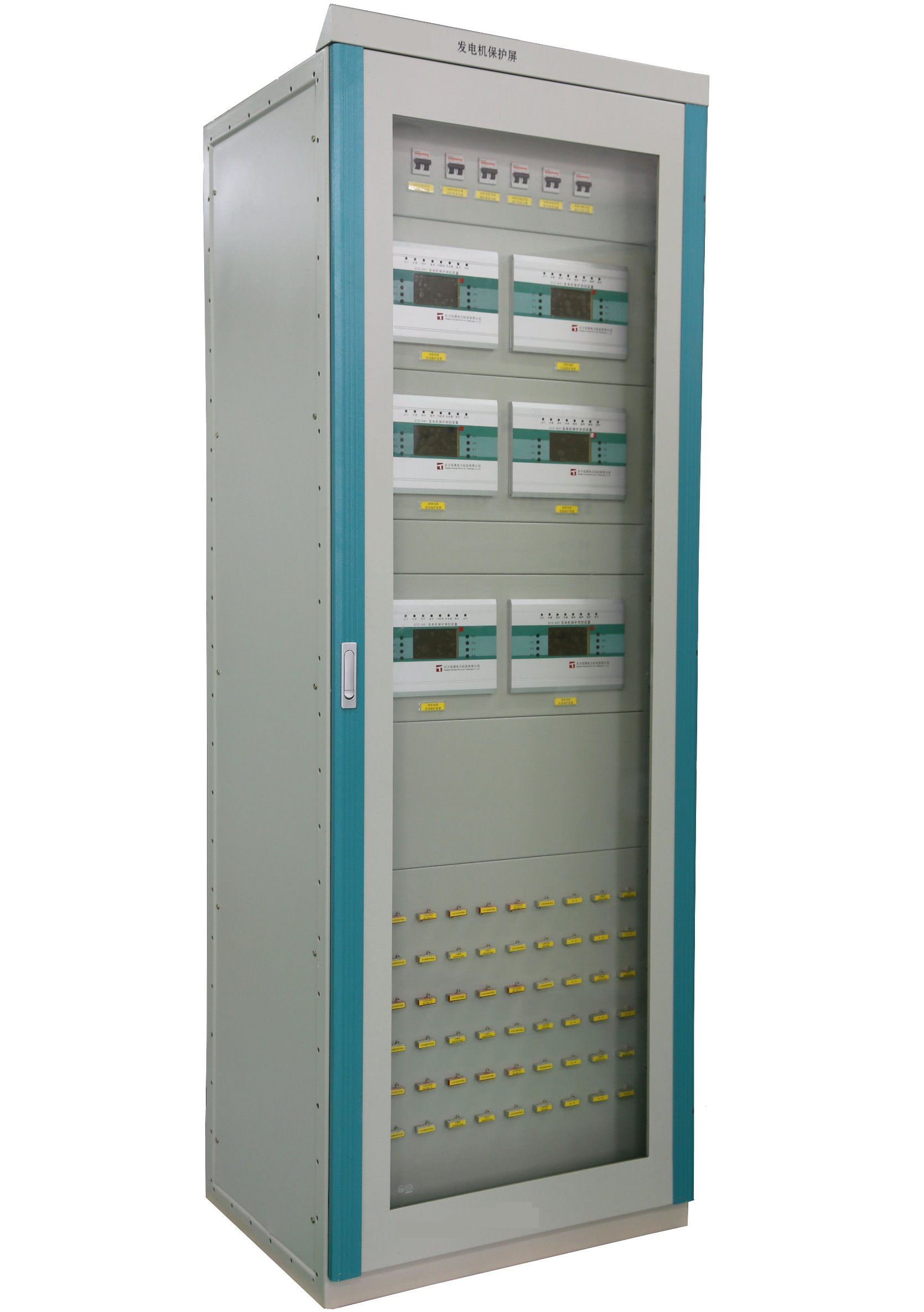
| 2.3.0 | Approximate Dimensions (Height, Width, Depth) (,,) | Mm | Indicate | 2260*800*600mm(H*W*D) |
| 2.4.0 | Mounting | | Yes | Yes |
| 2.5.0 | Operating temperature | ° C | -10 to +55 | -25 to +55ºC |
| 2.6.0 | Storage temperature | ° C | -40 to +70 | -40 to +85ºC |
| 2.7.0 | Relative Humidity Range | % | 10 to 90 | <93% |
| 3.0.0 | TENSION AND CURRENT ANALOGUE INPUTS | | | |
| | Number of analog inputs | | 24 | 12 |
| 3.1.0 | Voltage inputs | | | |
| | - Number of entries | | Referring to Fig. | |
| | - Rated voltage (Vn) | Vac | 110 | 110V |
| | - Operating margin | Vac | 0 - 340 | |
| | - Maximum permanent voltage | Vac | 420 | 420V rms |
| | - Maximum tension for 10 seconds | Vac | 450 | 450V rms |
| | Burden | GOES | <.02 To 110 Vac | <0.05 VA |
| 3.2.0 | Current Inputs | | | |
| | - Number of entries | | fifteen | 6 |
| | - Rated current (In)
(IN) | Amp. | 1 | 1/5A |
| | - Operating margin | Amp. | (0-100) x In | |
| | - Maximum permanent current | Amp. | 4 In | 20A |
| | - Maximum current for 1 sec. | Amp. | 100 In | 500A |
| | Burden | GOES | <0.02 to 1A | <0.05 VA
|
| 4.0.0 | DEPARTURES AND BINARY ENTRIES | | Yes | Yes |
| 4.1.0 | Programmable Trip and Signaling Outputs | | | |
| | - Number of contacts (minimum)
-() | No. | 24 | 24 |
| | - Maximum operating voltage
- | Vac / Vdc | 250 Vac, Vdc | 250 Vac, Vdc |
| | - Test voltage at the open contact, for 1 min.
-,1. | Vrms | 1000 | Meet |
| | - Permanent current carrying capacity
- | TO | Referring to Fig. | 5A |
| | - Current carrying capacity for 1 sec
- 1s | TO | 10 | 10A (3s)
10A (0.5s) |
| | - Cutting capacity | TO | 110 V / 0.4 A | 48V / ≤0.5 A
110V / ≤0.1 A
220V / ≤0.04 A |
| 125V / 0.35A |
| | - Closing capacity | TO | 30 A (for 0.2 s) 10 A (per 1.0 s) | Meet |
| 4.2.0 | Inputs | | | |
| | - Programmable input contacts | | Yes | Yes |
| | - Number of input contacts (minimum)
() | No. | 32 | Max.50 |
| | - Voltage range | V | 24 - 250 | 24...250 V DC |
| | - Power consumption per input | W | 0.2 W to 125 V | <0.3 W |
| 4.3.0 | LED's of signaling | | Yes | Yes |
| | - relay status | | 3 | Meet |
| | - the performance of the protection functions
- | | 15 (6 red and 9 yellow)
15(69) | 15 |
| 4.5.0 | Interfaces | | | |
| | - Large HMI on the relay front panel
HMI | | Yes | Yes |
| | - Front Ethernet port, PC connection
-,PC | | 1 port, RJ45 | 1 port, RJ45 |
| | - Ethernet optical port for remote communication | | 1 port, ST | Meet |
| 4.6.0 | Remote Communication | | | |
| | - Communication protocol | | IEC 61850 | IEC 61850 |
| | - Communication speed | MBps | 100 | 100 MBits/s |
| 5.0.0 | AUXILIARY SUPPLY | | | |
| 5.1.0 | Auxiliary Rated Voltage | Vcc | 90 to 250 | 88...300 V DC |
| 5.2.0 | Tolerance | % | ± 20% | 15% |
| 5.3.0 | Typical Consumption | | | |
| | - In normal operating condition
- | W | fifty | 30W |
| 5.4.0 | Auxiliary insertion power | TO | <5 A, for 0.1 sec | <5 A, for 0.1 sec |
| 6.0.0 | SPECIAL TESTS | | | |
| 6.1.0 | EMC Immunity (IEC 60255-22; 22-1; 22-2; 22-3; 22-4)
(IEC 60255-22;22-1;22-2;22-3;22-4) | | Yes | Yes |
| 6.2.0 | EMC Emission (IEC 60255-22, IEC 61000-4, IEEE / ANSI C37.90)
(IEC 60255-22,IEC 61000-4,IEEE / ANSI c37.90) | | Yes | Yes |
| 6.3.0 | Insulation (IEC 255-5)
(IEC 255-5) | | Yes | Yes |
| 6.4.0 | Mechanical Efforts IEC255-21, IEC68-2
iec255-21,iec68-2 | | Yes | Yes |
| 6.5.0 | Environmental Testing IEC60068, IEC68-2
iec60068,iec68-2 | | Yes | Yes |
| 7.0.0 | PROTECTION FUNCTIONS | | | |
| 7.1.0 | List of included functions | | | |
| | Transformer Differential (87T) | | Yes | Yes |
| | Distance between phases and ground phase (21 / 21N)
(21/21 n) | | Do not | No |
| | Phase overcurrent and ground phase (50/51, 50 / 51N) | | Yes | Yes |
| | Directional phase and ground phase overcurrent (67 / 67N) | | Yes | Yes |
| | Minimum and maximum voltage (27/59)
(27 / 59) | | Yes | Yes |
| | Bay controller up to 30 devices (6 switches)
30(6) | | Do not | Do not |
| | Switch failure (50BF)
(50bf) | | Yes | Yes |
| | Overexcitation (24)
(24) | | Yes | Yes |
| | Synchronization check (25)
(25) | | Yes | Yes |
| | Thermal Overload (49)
(49) | | Yes | Yes |
| | Frequency (81)
(81) | | Yes | Yes |
| | Fault Recording and Oscillographs (RF / RO) | | Yes | Yes |
| 7.2.0 | Transformer Differential (87T) (87t) | | | |
| | - Operation characteristic
- | | Adaptable | Yes |
| | - Precision | In | ± 2.0%, for I | ± 1.0% of Irr for I < Ir
± 1.0% of I for I > Ir |
| | - Sensitive base function | In | 10-60% | (4.0-100.0)% of IBase |
| | - Unrestricted differential current limit | In | 100-5000 | 90-6000 |
| | - Second Harmonica Restriction | fundamental | 5.0 - 100% | |
| | - Fifth Harmonica Restriction | fundamental | 5.0 - 100% | |
| | - Connection type of each winding | | Y, star or D, Delta | Y |
| | - Phase shifting between the High Dev W1 and each of the W2, and W3 windings
| notation | 0 - 11 | |
| Time |
| | - Operating time, restricted function | Ms | 25, t Ipeak of 0 to 2 x Id | 25 ms typically at 0 to 10 x IdMin |
| 7.3.0 | Phase and ground phase instantaneous overcurrent (50 / 50N) (50/50N) | | | |
| | - Adjustment steps (minimum) | | 1 | |
| | - Operating current range | % Ibase | (1 to 2500)% Ibase | |
| | - Operation time | Ms | 25 ms (0 to 2 Iset) | |
| 10 ms (0 to 10 Iset) | |
| | - Replacement time
| Ms | 25 ms (0 to 2 Iset) | |
| 35 ms (0 to 10 Iset) | |
| 7.4.0 | Phase overcurrent phase (51/67) and ground phase (51N / 67N) (51 / 67)(51n / 67n) | | | |
| | - Adjustment steps
| | 4 | |
| | - Operating current range | % In | (1 to 2500)% Ibase | (5-2500)% of lBase |
| | - Minimum operating current | | (1-100)% Ibase | Meet |
| | - Characteristic angle of relay 51/67 | Degrees | -70 to -50 | Meet |
| | - Maximum forward angle | Degrees | 40-70 | Meet |
| | - Minimum forward angle | Degrees | 75 to 90 | Meet |
| | - Characteristic angle of the relay 51N / 67N | Degrees | -180 to 180 | Meet |
| | - Blocking per second harmonic | % | (5-100%) of the fundamental | Meet |
| | - Timing | Sec | 0 to 60 | 0 to 60 |
| | ANSI timing curves
ANSI | | ANSI (Extremely Inverse, Very Inverse, Normal Inverse, Moderately Inverse, Extremely Inverse of Long Time, Very Inverse of Long Time, Inverse of Long Time)
ANSI(,,,,,,) | Meet |
| | IEC Timing Curves
IEC | | IEC (Normal Inverse, Very Inverse, Inverse, Extremely Inverse, Extr. Inverse Long time Inverse Short Time, Inverse Long Time)
IEC(,,,,.,) | Meet |
| | - Operating time, start function
-, | Ms | 25 (from 0 to 2 Iset) | 20 ms typically at 0 to 2 x Iset |
| | - Reset time, start function
-, | Ms | 25 (2 to 0 Iset) | 35 ms typically at 2 to 0 x Iset |
| 7.5.0 | Minimum voltage (27) | | | |
| | - Number of adjustment steps
| | 2 | Meet |
| | - Low and high setting range for operating voltage | % UBASE | 1 -100 | (1-100)% of UBase |
| | - Setting range for absolute hysteresis | % UBASE | 0 -100 | 0 -100 |
| | - Low and high setting range for internal lock level | % UBASE | 1 -100 | 1 -100 |
| | - Timing
| S | Definite Time (0-60) sec | (0.00 - 6000.00) s |
| Programmable Curves | Yes |
| | - Operating time for start-up function
| Ms | 25, t Ipeak 2 to 0 x Uset | 30 ms typically at 2 to 0.5 x Uset |
| | - Reset time for start-up function
| Ms | 25, t Ipeak from 0 to 2 x Uset | 40 ms typically at 0.5 to 2 x Uset |
| 7.6.0 | Maximum voltage (59) and Maximum residual voltage | | Yes | Yes |
| | - Number of adjustment steps
- | | 2 | 2 |
| | - Low and high setting range for operating voltage
- | % U base | 1 - 200 | (1-200)% of UBase |
| | - Setting range for absolute hysteresis
| % UBASE | 0 - 100 | 0 - 100 |
| | - Timing
| | Definite Time (0-60) sec | (0.00 - 6000.00) s |
| Programmable Curves | Yes |
| | - Operating time for start-up function
| Ms | 25, t Ipeak from 0 to 2 x Uset | 30 ms typically at 0 to 2 x Uset |
| | - Reset time for start-up function
| Ms | 25, t Ipeak 2 to 0 x Uset | 40 ms typically at 2 to 0 x Uset |
| 7.7.0 | Switch failure (50BF) | | | |
| | - Phase current adjustment range | % | (5-200)% Ibase | (5-200)% of lBase |
| | - Residual current adjustment range | % | (2-200)% Ibase | (2-200)% of lBase |
| | - Timers | Sec | 0 to 60 | (0.000-60.000) s |
| | - Operating time for current detection (typical)
() | Ms | 10 | 35 ms typically |
| | - Reset time for current detection (maximum)
() | Ms | fifteen | 10 ms maximum |
| 7.8.0 | Overexcitation (24) (24) | | | |
| | - Operating setting range for start up | UBase / fn | (100-180)% | (100-180)% of (Ubase/frated) |
| | - Setting range of operation for alarm | Ubase | (0-100)% | (50-120)% of start level |
| | - Operating setting range for high level
- | UBase / fn | (100-200)% | (100-200)% of (Ubase/frated) |
| | - Alarm timing | S | (0.000 - 60.000) | (0.000-60.000) s |
| 7.9.0 | Synchronization check (25) (25) | | Yes | Yes |
| | - Bar angle offset and line | degrees | -180 to 180 | -180 to 180 |
| | - Ubarra / Uline tension ratio | % | (0.40 - 5.00)% of UBASE | (0.40 - 5.00)% of UBASE |
| | - Setting range of the line-to-line frequency difference limit | Hz | 0.003 - 1 | 0.003 - 1 |
| | - Range adjustment of the line angle difference limit bar-line | degrees | (5.0 to 90.0) | (5.0 to 90.0) |
| | - Bar-line voltage difference limit adjustment range | % | (2.0 - 50.0)% of UBASE | (2.0 - 50.0)% of UBASE |
| | - Output timing for synchronization | S | (0.000 - 60.000) | (0.000 - 60.000) |
| | - High voltage limit setting range | % | (50-120)% of UBASE | (50-120)% of UBASE |
| 7.10.0 | Thermal Overload (49) (49) | | | |
| | - Base Current Setting Range | I base | (30-250)% | (30-250)% of IBase |
| | - Alarm setting | % I shot | (50-99)% | (50-99)% of heat content trip value |
| | - Operating current adjustment range | I base | (50-250)% | (50-250)% of IBase |
| 7.11.0 | Frequency (81) (81) | | | |
| | - Number of steps
| | 6 | Meet |
| | - Frequency Functions
| | M INIMA Frequency | |
| About Frecuencia | |
| Derived from Frequency | |
| | - Adjustment range
- | Hz | (35.00 - 75.00) | (35.00-75.00) Hz |
| | CONSTRUCTIVE ASPECTS | Hz / s | (-10,000 - 10.00) steps 0.01 | Meet |
| | Frequency | Ms | 100 | Meet |
| | Weight | S | (0.000 - 60.000) | 300kg |
| | Approximate Dimensions (Height, Width, Depth)
(,,) | S | Yes | |
| | Mounting | | Yes | |
| 7.12.0 | Operating temperature | | Yes | |
| | Storage temperature | S | 0.05 - 1 | -40...+85ºC |
| | Relative Humidity Range | S | 0.1 - 10 | <93% |
| | TENSION AND CURRENT ANALOGUE INPUTS
| S | 0.5 - 10 | 1A/5A |
| | Number of analog inputs | No. | 96 | 10~20 |
| | Voltage inputs | No. | 40 | |
| | - Number of entries
- | Sample / cycle | twenty | |
| | - Rated voltage (Vn)
(V) | Hz | 5 - 300 | |
| | - Operating margin | No. | 100 | |
| 8.0.0 | - Maximum permanent voltage | | | |
| 8.1.0 | - Maximum tension for 10 seconds | | | |
| | Burden | | Yes | |
| | Current Inputs | | Yes | |
| 8.2.0 | - Number of entries
- | | | |
| | - Rated current (In)
(IN) | | Yes | |
| | - Operating margin | | Yes | |
| 8.3.0 | - Maximum permanent current | | | |
| | - Maximum current for 1 sec. | | 1000 | |
| | Burden | | Yes | |
| | DEPARTURES AND BINARY ENTRIES | No. | 96 | |
| | Programmable Trip and Signaling Outputs | No. | 40 | |
| | - Number of contacts (minimum)
-() | Ms | 1 | |
| 8.4.0 | - Maximum operating voltage
- | | YES | |
| 8.4.1 | - Test voltage at the open contact, for 1 min.
-,1. | | | |
| | - Permanent current carrying capacity
- | | Yes | |